In the world of precision manufacturing, few processes are as critical as slicing hard materials into thin, uniform wafers. Whether it’s silicon for microchips, ceramic substrates for electronics, or rare-earth magnets for industrial applications, the wafer saw process is the backbone of modern microfabrication.
Silicon wafer slicing — also called silicon wafer sawing or simply the wafer cutting process — is the production step that turns a grown monocrystalline ingot into the thin discs used for chips and solar cells. If you are asking how silicon wafers are cut, the short answer is a diamond wire loop running at 10–25 m/s, where wafer thickness and total thickness variation (TTV) are set by wire tension and feed rate. The same physics governs cutting silicon wafers for photovoltaics and for semiconductor substrates; only the thickness target and the tolerance for subsurface damage differ.
But the wafer saw process isn’t a single method. It includes techniques likeダイヤモンドワイヤーループ 切断, EDM wire cutting, and even compact table top cutter machines for R&D and small-batch production.
重要なポイント
A diamond wire loop cuts silicon with a 100–300 µm steel wire electroplated or resin-bonded with diamond grit, running at 10–25 m/s under continuous coolant.
Diamond wire replaced ID blades and slurry sawing mainly because of kerf loss — a narrower cut means more wafers per ingot, which is the dominant cost lever in silicon.
The three defect modes to control are wire breakage and wear, surface micro-cracks, and wire bow caused by uneven tension.
Silicon wafer slicing, silicon wafer sawing and the wafer cutting process all describe the same production step: cutting silicon wafers from a monocrystalline ingot with a diamond wire. Production targets are typically 120–250 µm kerf loss with TTV held under 10 µm.
– EDM wire cutting as an alternative for conductive materials
– Table top cutter machines for laboratory and prototyping use
Let’s dive in:
1. What is a Wafer?
Before discussing how wafers are cut, we need to understand what a wafer actually is.
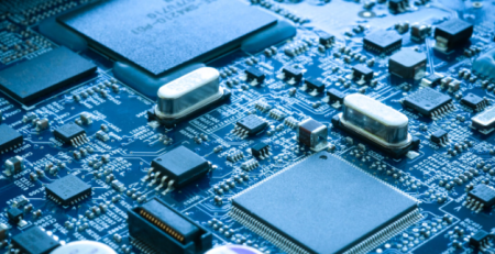
A wafer is a thin, flat disc of semiconductor material — most commonly silicon — on which microelectronic devices are built. Wafers serve as the substrate for integrated circuits (ICの), 太陽電池, LEDs, and MEMS (microelectromechanical systems).
Thickness is typically between 500–800 microns, but after polishing and backgrinding, finished IC wafers can be as thin as 50–100 microns.
Why Precision Cutting Matters
A single wafer can yield thousands of individual chips (dies). If the cutting process (dicing) is inaccurate, you lose chips, reduce yield, and increase costs. That’s why the wafer saw process must be extremely precise — often within ±1–5 microns.
2. Wafer Saw Process (ダイヤモンドワイヤーループ)
Now let’s focus on the core of our topic: the wafer saw process using aダイヤモンドワイヤーループ.
Traditional vs. Diamond Wire Sawing
Historically, wafers were cut from ingots using inner-diameter (ID) blades — circular saws with diamond-impregnated rims. But ID blades have limitations:
– Wide kerf (material loss)
– Slow cutting speed
– Surface damage
Enter diamond wire sawing.
How Diamond Wire Loop Works
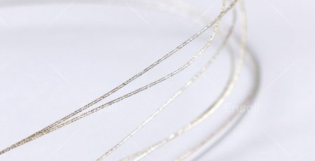
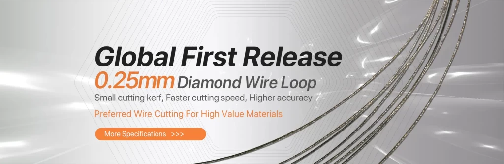
A diamond wire loop consists of a thin steel wire (typically 100–300 microns in diameter) electroplated or resin-bonded with diamond grit. The wire is formed into a continuous loop and driven by pulleys at high speed (10–25 m/s).
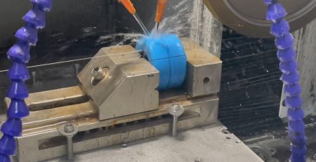
As the wire moves, the diamond grit grinds through the material via a three-body abrasion mechanism. Coolant (usually deionized water or oil-based fluid) removes debris and heat.
Key Advantages of Diamond Wire Loop for Wafer Sawing
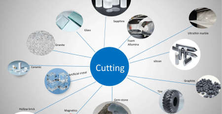
Diamond wire loop sawing isn’t only for シリコンウエハ. It’s also used for:
– 炭化ケイ素 (ティッカー) – wide-bandgap semiconductor
– ガリウム砒素 (GaAsの) – RF and LED applications
– Sapphire – for LED substrates and watch crystals
– Ceramic substrates – alumina, zirconia
– Quartz and glass – optical and MEMS wafers
3. EDM Wire Cutting (A Complementary Technology)
While diamond wire sawing is excellent for non-conductive and hard materials, EDM wire cutting (放電加工) offers a completely different mechanism.
What is EDM Wire Cutting?
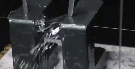
EDM wire cutting uses a thin, electrically charged brass or copper wire to erode conductive materials through a series of rapid electrical sparks. The wire never touches the workpiece — instead, sparks jump across a small gap, melting and vaporizing tiny particles.
How It Works
Wire electrode (0.05–3 mm diameter) スプールから連続供給される.
Deionized water acts as a dielectric fluid, flushing away debris and controlling sparks.
CNC controls move the workpiece relative to the wire.
Sparks occur thousands of times per second, gradually cutting through metal.
When to Use EDM Wire Cutting vs. Diamond Wire Sawing
材料の種類
Recommended Method
珪素, セラミック, グラス, サファイア
ダイヤモンドワイヤーループ
Steel, 超硬合金, チタン, Inconel
EDM wire cutting
磁性材料 (NdFeB, SmCo)
Both possible; EDM avoids mechanical stress
PCD (polycrystalline diamond)
放電加工 (diamond is conductive if doped)
Advantages of EDM Wire Cutting
No mechanical contact → no stress or burrs
Cuts extremely hard metals (HRC 60+)
高精度 (±1–2 microns)
Can cut complex 2D shapes (not just straight slices)
While EDM is rarely used to slice silicon ingots (silicon is only semi-conductive and EDM works poorly on high-resistivity Si), it is used for:
Cutting metalized ceramic substrates
Dicing copper-clad laminates
Slicing tungsten, molybdenum, or Kovar parts used in semiconductor
4. Table Top Cutter Machine
Not every wafer or material cutting job requires a massive industrial saw. For R&D labs, universities, small foundries, and prototype shops, a table top cutter machine is the perfect solution.
Typical Features
Compact footprint (fits on a lab bench)
Adjustable cutting speed and feed rate
Small cutting capacity (typically up to 50–100 mm diameter ingots or blocks)
Integrated coolant system (recirculating or gravity-fed)
Digital readout or CNC control (on high-end models)
Minimal waste – ideal for expensive materials like GaAs or SiC
1. Understanding Monocrystalline Silicon
Before diving into the cutting process, let’s briefly discuss monocrystalline silicon and why it requires specialized cutting techniques.
1.1 What is Monocrystalline Silicon? (You can also click the link to learn more details via Wikipedia.)
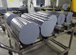
Monocrystalline silicon is a highly pure form of silicon with a single, continuous crystal lattice structure. It is produced using the Czochralski (CZ) method or the Float Zone (FZ) 方式, resulting in cylindrical ingots.
1.2 Why Precision Cutting is Critical
– 半導体産業: Silicon wafers must have ultra-smooth surfaces(nanometer-level roughness) for microchip fabrication.
-Photovoltaic Industry: Solar cells require thin, uniform wafers(typically 160-180µm) to maximize efficiency.
– Minimal Kerf Loss: Reducing material waste during cutting improves cost efficiency.
Traditional cutting methods like ID saws (inner diameter saws) and multi-wire slurry saws have been replaced by diamond wire saw cutting due to superior performance.
4. Challenges & Solutions in Diamond Wire Saw Cutting
Despite its advantages, ダイヤモンドワイヤーソーfaces some challenges:
The wafer saw process is a cornerstone of modern electronics manufacturing. From growing For conductive materials, EDM wire cutting offers a complementary non-contact method capable of slicing hardened steels, carbides, and superalloys with micron-level accuracy.
And for those working in R&D, prototyping, or small-scale production, a table top cutter machine provides an affordable, flexible entry point into high-precision cutting — without the floor space or budget of an industrial wire saw.
Whether you’re manufacturing 300mm silicon wafers for AI processors or cutting a small alumina substrate on a lab bench, understanding the strengths and limitations of diamond wire loop, 放電加工, and table top cutters will help you select the right tool for the job.a silicon ingot to slicing it into hundreds of thin wafers using a diamond wire loop, every step demands precision, cleanliness, and reliability.
よくある質問
シリコンウェハーはインゴットからどのように切り出されるのか?
The ingot is grown by the Czochralski or Float Zone method, ground to a precise diameter, then sliced by a diamond wire loop. After sawing, wafer edges are chamfered to prevent chipping, and the wafers are lapped and polished.
TTVとはウェハーカットにおいて何か?
TTV (total thickness variation) is the difference between the thickest and thinnest points on a wafer. It is the headline metric for wafer sawing quality because downstream lithography needs a flat, uniform surface.
なぜダイヤモンドワイヤーがスラリー切断に取って代わったのか?
Fixed-diamond wire gives a narrower kerf, a cleaner process with no loose abrasive to manage, and more wafers per ingot. Slurry sawing wastes more silicon per cut and carries higher consumable and disposal costs.
薄いウェハーを切る際に破損を制御する要素は何か?
Real-time tension monitoring, correctly sized diamond grit, and clean filtered coolant. As wafers drop below 150 µm, tension stability and feed control matter more than cutting speed.
What is the difference between diamond wire sawing and EDM wire cutting for wafers?
Diamond wire cuts non-conductive and hard materials with a 120–250 µm kerf at 2–10 mm/min and Ra 0.2–0.5 µm. EDM wire cutting only works on conductive materials, is slower at 0.5–3 mm/min, but produces a finer finish of Ra 0.05–0.2 µm.
What wire diameter is used for silicon wafer cutting?
Typically 100–300 µm steel core wire, carrying diamond grit in the 30–100 µm range, applied by electroplating or resin bonding. Thinner wire reduces kerf loss but needs tighter tension control.
How thin can silicon wafers be cut?
Production solar wafers are commonly 160–180 µm, next-generation cells are moving below 150 µm, and sub-100 µm wafers are the current development target. Each step down demands finer wire and tighter process control.
What causes wire bow, and how is it corrected?
Wire bow is a wavy cut caused by uneven wire tension across the cut. It is corrected with advanced wire guidance systems that apply dynamic tension control throughout the cut.
Technical content reviewed by the Ensoll engineering team — a diamond wire loop manufacturer with 10+ years of production experience.
Ferrite materials are everywhere in modern technology. From the tiny magnetic components inside your smartphone to the powerful electromagnets in... 続きを読む
Key Takeaways
Precision cutting is paramount in semiconductor manufacturing because slicing damage propagates into every downstream process.
異なる半導体材料は異なる...が必要です。. 続きを読む

 Typical Wafer Sizes
 What is EDM Wire Cutting?
 Monocrystalline silicon is a highly pure form of silicon with a single, continuous crystal lattice structure. It is produced using the Czochralski (CZ) method or the Float Zone (FZ) 方式, resulting in cylindrical ingots.