Slicing Magnetic Materials with Endless Diamond Wire Saw
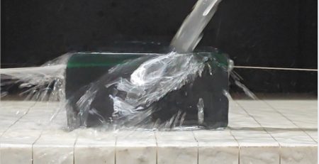
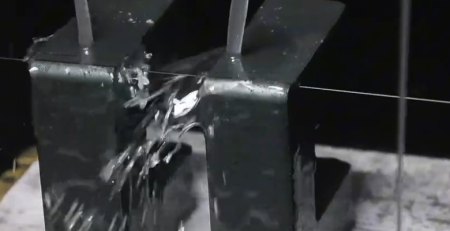
Test scope: Precision straight slicing of a cylindrical magnetic-material sample supplied by a European customer, using an Ensoll ESO-GM endless diamond wire saw.
- Five 3.780 mm slices cut from a 15 mm magnetic-material cylinder held within-slice TTV of 0.008-0.011 mm, averaging 0.009 mm.
- Average surface roughness stayed between Ra 0.71-0.88 micrometers and maximum edge chipping was 9.2 micrometers — a stable, finishing-ready cut.
- Average slice thickness drifted downward across the sequence (-0.083 mm by slice five), so batch production needs thickness-offset or wire-bow compensation.
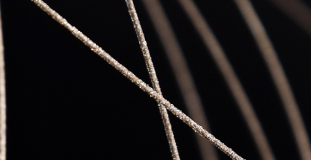
- The result came from a matched system: a rigid gantry machine with real-time tension control, a 0.5 mm fully coated diamond wire loop and cutting-oil cooling.
Magnetic materials are hard and brittle, with relatively low fracture toughness. During slicing, cutting force, frictional heat, and internal stress can cause edge chipping, microcracks, thickness variation, and surface damage. This test evaluated whether an endless diamond wire process could maintain stable slice geometry and surface integrity while cutting a 15 mm diameter sample.
Where the workpiece is NdFeB rather than ferrite, the settings in our how to cut neodymium magnets guide are the safer starting point.
Measured Results at a Glance
- Workpiece: Magnetic material, approximately Mohs 6-7
- Sample dimensions: 15 mm diameter x 103 mm length
- Nominal slice thickness: 3.780 mm
- TTV: 0.008-0.011 mm across five slices; average 0.009 mm
- Average surface roughness (Ra): 0.71-0.88 micrometers
- Maximum measured edge chipping: 6.7-9.2 micrometers by slice
The results show good thickness uniformity within each individual slice and consistently low surface roughness. The gradual change in average thickness across the five slices also identifies an important process-control opportunity: tighter multi-slice batch consistency would require offset or feed compensation during production.
1. Test Objective and Process Strategy
The customer required high-precision straight slicing with controlled thickness variation, surface roughness, and edge damage. Ensoll selected the ESO-GM endless diamond wire saw, cutting oil, and a fully coated diamond wire loop as a matched process system.
Cutting oil was used to improve lubrication and heat removal in the cutting zone. The fully coated wire provides a stable abrasive distribution and consistent material removal, while the machine’s tension-control system helps reduce wire-position fluctuation during the cut.

2. Equipment and Cutting Parameters
The ESO-GM uses a rigid gantry structure with top-down vertical feed. Its integral cast-iron frame is designed to limit vibration and structural deformation during long cutting cycles. The system also includes real-time tension control, wire-break position memory, and mist extraction for oil-cooled processing.
| Parameter | Test Setting |
|---|---|
| Machine | ESO-GM endless diamond wire saw |
| Wire diameter | 0.50 mm |
| Diamond wire loop length | 1930 mm |
| Feed-rate setting | 2 / 1 mm/min |
| Cutting width | 15 mm |
| Wire tension | 180 N |
| Linear wire speed | 26 m/s |
| Wire-bowing time | 100 s |
| Recorded cutting load | 25 N·m |
| Cooling and lubrication | Cutting oil |
Customers evaluating similar hard and brittle components can also review Ensoll’s magnetic-material cutting machines and diamond wire loops.


3. Total Thickness Variation (TTV)
Each slice was measured at nine positions using a vacuum-chuck, dual-probe thickness measurement method. The TTV value is the difference between the maximum and minimum measured thickness on the same slice.
| Sample | Nine-Point Thickness Measurements (mm) | Tmax | Tmin | TTV |
|---|---|---|---|---|
| S01 | 3.784, 3.781, 3.786 / 3.779, 3.782, 3.785 / 3.780, 3.783, 3.778 | 3.786 | 3.778 | 0.008 |
| S02 | 3.792, 3.788, 3.790 / 3.786, 3.789, 3.791 / 3.787, 3.793, 3.785 | 3.793 | 3.785 | 0.008 |
| S03 | 3.775, 3.778, 3.781 / 3.772, 3.776, 3.779 / 3.774, 3.780, 3.773 | 3.781 | 3.772 | 0.009 |
| S04 | 3.741, 3.745, 3.748 / 3.739, 3.743, 3.746 / 3.740, 3.744, 3.742 | 3.748 | 3.739 | 0.009 |
| S05 | 3.695, 3.699, 3.703 / 3.692, 3.696, 3.701 / 3.694, 3.698, 3.697 | 3.703 | 3.692 | 0.011 |
Interpretation: TTV remained between 0.008 and 0.011 mm, with an average of 0.009 mm. This indicates stable local thickness uniformity within each slice.
4. Average Thickness and Dimensional Drift
The nominal slice thickness was 3.780 mm. Average thickness was calculated from the nine measurements for each sample.
| Sample | Average Thickness (mm) | Deviation from 3.780 mm |
|---|---|---|
| S01 | 3.782 | +0.002 mm |
| S02 | 3.789 | +0.009 mm |
| S03 | 3.776 | -0.004 mm |
| S04 | 3.743 | -0.037 mm |
| S05 | 3.697 | -0.083 mm |
Interpretation: The observed deviations ranged from -0.083 to +0.009 mm. Although the within-slice TTV remained stable, the average thickness decreased over the sequence. For applications with a tight batch-level thickness tolerance, this trend should be addressed through programmed thickness-offset compensation, feed adjustment, or wire-bow compensation.
5. Surface Roughness
Surface roughness was measured with a stylus profilometer at three representative positions on each cut surface, following the Ra definition in ISO 4287.
| Sample | Ra-1 | Ra-2 | Ra-3 | Average Ra (micrometers) |
|---|---|---|---|---|
| S01 | 0.81 | 0.85 | 0.79 | 0.82 |
| S02 | 0.74 | 0.78 | 0.76 | 0.76 |
| S03 | 0.69 | 0.73 | 0.71 | 0.71 |
| S04 | 0.86 | 0.91 | 0.88 | 0.88 |
| S05 | 0.77 | 0.82 | 0.79 | 0.79 |
Interpretation: Average Ra remained within 0.71-0.88 micrometers. The narrow range indicates a stable abrasive cutting state and a consistent surface suitable for subsequent precision finishing.
6. Edge-Chipping Results
Edge chipping was measured at four positions on each slice using an optical tool microscope.
| Sample | Position 1 | Position 2 | Position 3 | Position 4 | Maximum Chipping (micrometers) |
|---|---|---|---|---|---|
| S01 | 5.2 | 7.1 | 4.6 | 6.3 | 7.1 |
| S02 | 4.8 | 6.5 | 5.6 | 7.4 | 7.4 |
| S03 | 4.1 | 5.8 | 5.0 | 6.7 | 6.7 |
| S04 | 6.3 | 9.2 | 5.8 | 8.6 | 9.2 |
| S05 | 5.1 | 7.6 | 6.2 | 8.1 | 8.1 |
Interpretation: The largest measured chip was 9.2 micrometers, and the average of the five maximum values was 7.7 micrometers. The edges remained visually intact with limited brittle-fracture damage.

7. Engineering Conclusion
This test demonstrates that the ESO-GM endless diamond wire process can produce magnetic-material slices with low within-slice TTV, consistent sub-micrometer Ra values, and limited edge chipping. The combination of a rigid machine structure, real-time tension control, a fully coated diamond wire loop, and oil cooling supported a stable cutting condition.
The data should also be read carefully: TTV describes uniformity within each slice, while the average thickness values show a downward trend across the five-slice sequence. Before volume production, the process should therefore be validated against the customer’s drawing tolerance and, where necessary, supplemented with automatic thickness or wire-bow compensation.
For a different magnetic-material machining requirement, see Ensoll’s irregular-profile magnetic-material cutting test.
Citation permission: If you find this article helpful, Ensoll authorizes you to quote or reference it, provided that you include a link to this page as the original source.
Frequently Asked Questions
What is TTV in precision slicing and why does it matter?
TTV (total thickness variation) is the difference between the thickest and thinnest points on one slice. Low TTV means uniform slices, which reduces downstream lapping and keeps magnetic component tolerances tight. This test held TTV between 0.008 and 0.011 mm.
Why does slice thickness drift during multi-slice production?
As cutting progresses, wire wear and wire bow slowly change the effective cut position, so later slices can come out thinner or thicker. The fix is programmed thickness-offset compensation, feed adjustment, or wire-bow compensation before volume production.
What level of edge chipping is acceptable when slicing hard, brittle magnets?
It depends on the drawing, but single-digit micrometers is considered clean. In this test the largest measured chip was 9.2 micrometers and edges remained visually intact with limited brittle-fracture damage.
Why use cutting oil when slicing magnetic materials?
Cutting oil improves lubrication and heat removal in the cutting zone and helps evacuate swarf, which keeps the wire cutting stable and the workpiece cool throughout long slicing cycles.
Technical content reviewed by the Ensoll engineering team — a diamond wire loop manufacturer with 10+ years of production experience.