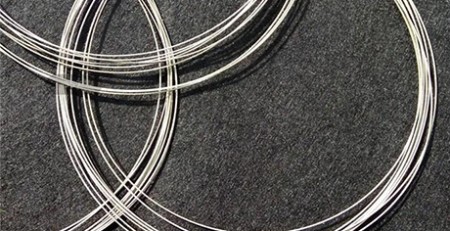
다이아몬드 와이어 루프를 이용한 광학 유리 정밀 슬라이스: 30.5 mm 막대 테스트 데이터
추상적인: This application report covers a high-precision straight-slicing test on optical glass
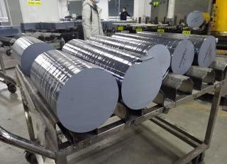
supplied by a European customer. The workpiece was a rod of 30.5 mm 직경, cut into sections 15 mm long on an
ESO-GM gantry diamond wire loop cutting machine, with cutting oil as the cooling medium and a fully coated diamond
wire. Measured results across three sections: total thickness variation (TTV) 0.003-0.008 밀리미터, thickness tolerance
±0.141 mm against a 15.000 mm nominal, surface roughness Ra 0.58-1.06 μm의, and maximum edge chipping
4.9-6.2 μm의. Matching machine structure, the oil cutting method, wire selection and process parameters to the
brittle behaviour of optical glass kept material removal stable and held section dimensional accuracy and cut-surface
quality inside a workable band.
주요 요점
- Optical glass is hard and brittle with low fracture toughness, so the failure modes in wire slicing are chipping,
미세 균열, end-face damage and thickness scatter — not tool wear. - A rod of 30.5 mm diameter was sliced into 15 mm sections on an ESO-GM gantry diamond wire loop machine, 와
cutting oil, a fully coated 0.35 x 1880 mm wire, 10 mm/min wire travel, 140 N tension and 24 m/s 와이어 속도. - TTV across the three sections came in at 0.003-0.008 밀리미터, so thickness variation stayed under 8 μm on a 15 밀리미터
section. - Average Ra ran 0.58-1.06 μm and maximum chipping 4.9-6.2 μm의, which points to a stable cutting state and
good edge integrity. - All three sections measured thick rather than thin, from +0.059 받는 사람 +0.141 밀리미터. That is a systematic offset, and it
is easier to take out with dimensional compensation than by touching the process.
Sample test for a European customer | Diamond wire loop cutting process
Overview of the Optical Glass Precision Slicing Test
This test was run on optical glass supplied by a European customer, with high-precision straight slicing as the
main requirement. Optical glass sits firmly in the hard, brittle family: hardness is fairly high, brittleness is
pronounced and fracture toughness is low. Once the diamond grains start abrading continuously, poor control of the
cutting load or of the temperature in the cutting zone concentrates stress inside the material, and that is where
chipping, 미세 균열, end-face damage and section dimensional deviation come from. The work therefore went at
machine structure, cutting method, wire selection and process parameters as one set, so the slicing stayed stable and
section dimensions and cut-surface quality could be held to the tolerances required for
광학 유리 절단.
Because optical glass asks for dimensional accuracy, end-face quality and edge integrity at the same time, 엔솔
applied a diamond wire loop process matched to those characteristics. On the machine side the choice fell on a
dedicated gantry diamond wire loop cutting machine. Its rigidity and running stability give the workpiece a firm
clamping base and hold the wire on a steady path, which cuts down the effect of machine vibration and motion error on
the cutting trajectory and on section dimensions. On the consumable side, a diamond wire matched to optical glass
keeps the grains removing material at a steady rate, so a change in wire condition does not turn into a change in
section quality. For cooling and lubrication, cutting oil was used: it improves lubrication and heat dissipation at
the contact zone between wire and glass, lowers friction and heat build-up through the cut, and reduces what a local
temperature rise does to the cut face. On top of that, wire running speed and feed rate were set against the
properties of the material and the target section length, keeping the cutting load inside a suitable band and avoiding
the local overload and edge breakage that an aggressive feed produces. Machine, wire, oil cutting and parameters
matched as one set kept the process stable and brought section dimensional accuracy, thickness consistency,
cut-surface quality and edge integrity under control — a workable process basis for high-precision straight
slicing of optical glass. The same parameter logic applied to flat work is set out in our
BG38 glass sheet slicing test.
1. Test Object: Basic Information
- 재료: 광학 유리
- 경도: approximately MH 6 받는 사람 7
- Workpiece dimensions: 직경 30.5 밀리미터
- Cut dimensions: 15 밀리미터 (L) x 30.5 밀리미터 (φ)
2. Machine and Wire Selection
Machine type: ESO-GM. Given the brittle behaviour of optical glass and the high-precision straight
slicing requirement, Ensoll selected the ESO-GM diamond wire saw, the gantry machine built
for this class of work. It holds running stability and trajectory accuracy through the cut, reduces the effect of
machine vibration and load fluctuation on machining quality, limits the chipping, micro-cracking and dimensional
deviation that uneven loading would otherwise produce, and so improves dimensional accuracy, cut-surface quality and
edge integrity in optical glass sections.
- Coolant type: cutting oil. Cutting oil is used as the cooling and lubricating medium. It improves
lubrication and heat dissipation in the contact zone, lowers friction and heat build-up through the cut, and reduces
the thermal and local stress variation the glass sees. That lowers the risk of chipping, micro-cracks and end-face
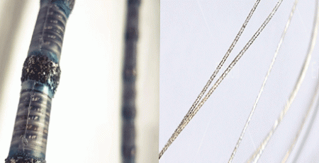
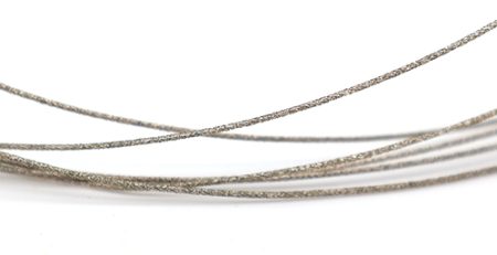
damage, which helps dimensional stability, surface quality and edge integrity. - Wire type: fully coated. A fully coated diamond wire raises the bond strength between grains and
the steel core and keeps grain distribution even, so the wire removes material continuously and steadily through the
cut. It reduces the effect of grain pull-out and wire wear on the cutting state, which limits dimensional variation
and edge damage when slicing optical glass.
3. 절단 방법 및 기계 장점
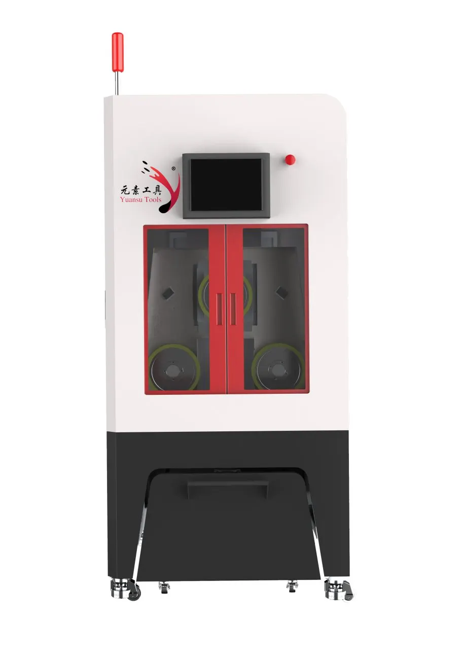
Gantry cutting method. The gantry structure gives the machine high overall rigidity and running
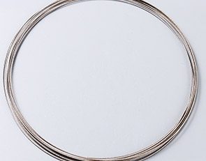
stability, and the top-down vertical feed helps keep the 다이아몬드 와이어 루프 on a stable
path, reducing the effect of load variation on kerf position and dimensional accuracy in optical glass sections. 이
machine also carries a mist extraction system that clears the oil mist produced during cutting, keeping the work zone
clean and the cutting area in good condition for a stable run.
지능형 장력 제어 시스템. The system adjusts wire tension in real time according to the
machining state and supports both constant-tension and variable-tension modes, so the wire runs steadily through the
cut. Stable tension reduces trajectory drift and cuts the risk of wire breakage that tension variation brings, which
narrows the local load changes seen at the cut and helps control section dimensions and edge quality across the
batch.
Breakpoint resume. If the wire breaks or the machine stops abnormally, the system records the
current cutting position and the associated running state. After a wire change the cut resumes from that position,
which reduces the re-positioning error and repeat cutting that would otherwise affect cut position and quality, and it
keeps material loss down while the slicing run stays continuous.
High-rigidity one-piece cast iron frame. The one-piece cast iron frame raises overall stiffness and
vibration resistance, lowering the effect of structural vibration and deformation on the wire path. For a hard,
brittle material such as optical glass, that rigidity reduces load fluctuation during the cut and gives the dimensional
정밀, cut-surface quality and edge integrity of precision slicing a reliable machine basis.
4. Parameter Settings and Cooling Method
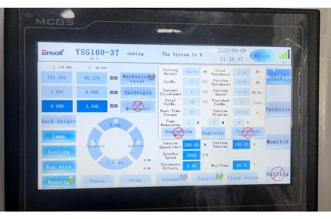
The parameter set below was used for the whole run, and the sections reported in section 5 all came off it. 와이어
tension and wire speed are the two settings that carry most of the load control; the cutting load reading is what the
operator watches to keep the wire inside its working band.
| 매개변수 | 값 |
|---|---|
| 와이어 직경 (밀리미터) | 0.35 x 1880 |
| Wire travel speed (mm / 분) | 10 |
| 절단 폭 (밀리미터) | 30.5 |
| Cutting wire tension (N) | 140 |
| 와이어 속도 (엠/초) | 24 |
| Wire-bow time (초) | 60 |
| 절단 부하 (N·m) | 20 |
5. Cutting Efficiency and Results
5.1 TTV 시험 데이터 (밀리미터)
TTV (총 두께 변동) was measured with a nine-point grid, dual-probe thickness method on a vacuum-chuck
stage, applied to sections produced by diamond wire loop cutting. The sections measured 15 밀리미터 (L) x 30.5 밀리미터 (φ),
with a nominal thickness of 15 밀리미터. Before measurement the instrument was thermally stabilised and calibrated with a
standard thickness block to reduce zero drift and systematic error. 무진 청소 후, each sample was centred
on the vacuum chuck and held by negative pressure, so that warping, tilt and position shift during measurement had
less effect on the thickness readings. Thickness data were then collected in sequence at the preset nine grid
positions, and the difference between the largest and the smallest reading across those points was taken as the TTV
of that sample, used to evaluate thickness uniformity and machining consistency. The procedure follows the method
explained in nine-point TTV measurement.
| 시료 | Nine-point thickness readings (밀리미터) | Tmax | Tmin | TTV |
|---|---|---|---|---|
| S01 | 15.056, 15.057, 15.058 / 15.059, 15.060, 15.061 / 15.062, 15.058, 15.057 | 15.062 | 15.056 | 0.006 |
| S02 | 15.112, 15.113, 15.114 / 15.115, 15.113, 15.114 / 15.113, 15.114, 15.115 | 15.115 | 15.112 | 0.003 |
| S03 | 15.135, 15.137, 15.138 / 15.140, 15.141, 15.142 / 15.143, 15.138, 15.139 | 15.143 | 15.135 | 0.008 |
평가: Looking at the nine-point readings for the three sections, S01 measured between 15.056
그리고 15.062 밀리미터, S02 between 15.112 그리고 15.115 mm and S03 between 15.135 그리고 15.143 밀리미터, giving TTV values of 0.006 밀리미터,
0.003 mm and 0.008 mm respectively. S02 held the tightest thickness uniformity and S03 showed the widest spread, but
every section stayed inside 0.008 밀리미터. Thickness variation across the measured areas is therefore small, which says the
wire ran steadily and the cutting state held through the run, and thickness consistency meets what high-precision
optical glass slicing asks for.
5.2 Thickness Tolerance Data (밀리미터)
Thickness tolerance was measured by the same nine-point grid method, 와 15.000 mm as the nominal thickness. 이
deviation of each measured point from nominal was calculated, and the maximum positive deviation, maximum negative
deviation and overall thickness tolerance were collated, to assess dimensional accuracy and machining consistency of
the optical glass sections.
| 시료 | 평균 두께 (밀리미터) | 두께 편차 (밀리미터) |
|---|---|---|
| S01 | 15.059 | +0.059 |
| S02 | 15.114 | +0.114 |
| S03 | 15.141 | +0.141 |
| 최대 양의 편차 | +0.141 | +0.141 |
| 최대 음의 편차 | 0 | 0 |
| 두께 허용 | ±0.141 | ±0.141 |
평가: 와 함께 15.000 mm as nominal, the three sections averaged 15.059, 15.114 그리고 15.141 밀리미터,
corresponding to deviations of +0.059, +0.114 그리고 +0.141 밀리미터. All three sat on the positive side, the maximum positive
deviation was +0.141 mm and no negative deviation was recorded, so the overall thickness tolerance is quoted as
±0.141 mm. Average thickness also rises steadily with sample number, which shows the batch carried a small
systematic bias towards the thick side. The bias is regular rather than random, so it is a compensation matter rather
than a process-capability one.
5.3 Surface Roughness Ra Data (μm의)
표면 거칠기 (Ra) was measured to ISO 4287 with a stylus profiler. Three representative positions were profiled
on the cut face of each section — centre, mid-left and mid-right — and Ra was calculated at each position
to assess the cut surface and machining quality.
| 시료 | Ra-1 | Ra-2 | Ra-3 | 평균 Ra |
|---|---|---|---|---|
| S01 | 1.02 | 1.08 | 1.07 | 1.06 |
| S02 | 0.55 | 0.61 | 0.58 | 0.58 |
| S03 | 0.82 | 0.91 | 0.88 | 0.87 |
평가: Measured by the three-point method, average Ra came out at 1.06, 0.58 그리고 0.87 μm의
for S01, S02 and S03, so the whole set falls in the 0.58-1.06 μm range. The difference between measuring
positions on a single section is small, which means the cut face is fairly even and the process holds surface quality
under control. S02, which also held the best TTV, returned the lowest Ra — the two indicators moved together on
this run.
5.4 Edge Chipping Data (μm의)
Chipping was measured by optical imaging on a toolmaker’s microscope to quantify edge defects on the sections, which
measured 15 밀리미터 (L) x 30.5 밀리미터 (φ) after cutting. Sample edges were cleaned before measurement, and the instrument
magnification and measuring scale were calibrated. The edge regions were then scanned under the microscope,
recognisable chips were located and measured, and the defect size at each point was recorded, giving an assessment of
edge quality and cutting performance.
| 시료 | 위치 1 | 위치 2 | 위치 3 | 위치 4 | 최대 칩핑 |
|---|---|---|---|---|---|
| S01 | 4.6 | 5.2 | 4.9 | 5.8 | 5.8 |
| S02 | 3.8 | 4.5 | 4.1 | 4.9 | 4.9 |
| S03 | 5.1 | 5.7 | 5.4 | 6.2 | 6.2 |
평가: Inspected by the four-point method, the largest chip measured 4.9-6.2 μm across
the three sections, with the individual measurement points sitting close together. Defect sizes are small and the
difference between samples is limited, which indicates a stable cutting state through the run and good edge integrity
on the sections.
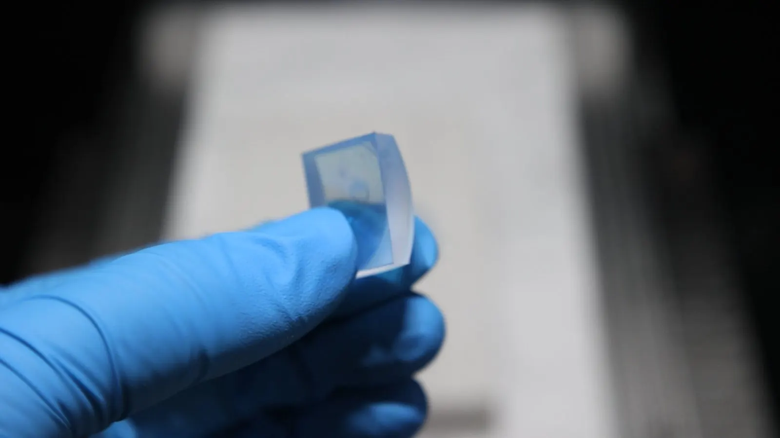
6. 결론
The optical glass in this run sliced well, and the result came mainly from matching a dedicated gantry machine, 이
oil cutting method and the process parameters as one set. Optical glass is a classic hard, brittle material: 경도
is fairly high, brittleness is pronounced and fracture toughness is low, and during diamond wire loop cutting the
continuous abrasion of the grains means that local cutting load and heat build-up easily concentrate stress, which
produces chipping, 미세 균열, an uneven cut face and section dimensional deviation. Aimed at the machining
behaviour of the material and the requirement for high-precision straight slicing, 기계 선정, cutting method
and parameters were all adjusted in a targeted way, holding section dimensional accuracy, thickness consistency and
cut-surface quality in check while the cutting process itself stayed stable.
첫째, 기계 선정. Given what optical glass slicing demands in motion stability, 기계
rigidity and cutting accuracy, 전용 간트리 다이아몬드 와이어 루프 절단기가 선택됨. The gantry structure
provides good overall rigidity and running stability, which gives the workpiece firm clamping and the wire a reliable
mechanical basis for steady running, 기계 진동 영향을 줄인다, motion error and wire running
fluctuation on the cutting trajectory. Stable feed and motion control also narrow the cutting-load variation, so wire
and glass stay in a comparatively steady relative motion, which lowers the risk of dimensional deviation and local
chipping and gives high-precision slicing a stable machine basis.
Second, cutting method. Optical glass is markedly brittle and sensitive to thermal effects during
절단, so oil cutting was used, with cutting oil as the cooling and lubricating medium. Cutting oil improves
lubrication and heat dissipation in the contact zone between wire and glass, lowering friction and heat build-up and
reducing the effect of local temperature rise and thermal stress on the material. Steady cooling and lubrication also
help hold the cutting zone in a consistent state and reduce the cutting fluctuation that friction or concentrated heat
would cause, so chipping, micro-cracks and end-face damage become less likely and the cut surface and edge integrity
improve.
Third, process parameters. Against the material properties and the target section size, wire
running speed and feed rate were matched accordingly. Parameters were set to keep the wire running stably and material
removal even, avoiding a feed rate so high that the cutting load climbs, and avoiding a combination that produces
국부 가열, stress concentration and brittle fracture. The targeted adjustment kept material removal comparatively
steady and, while still meeting machining efficiency, reduced impact and load fluctuation through the cut, which
improved thickness consistency, cut-surface quality and edge integrity.
Taken together, the results for section dimensional accuracy, thickness tolerance, 표면 거칠기 (Ra) 그리고
cut-edge quality show that, with a dedicated gantry cutting machine, oil cutting and suitable parameters working
together, diamond wire loop cutting meets the requirements of high-precision straight slicing for optical glass. 이
samples performed steadily in dimensional accuracy, thickness consistency, cut-surface quality and edge integrity,
which indicates that matching machine structure, cooling and lubrication method and process parameters to the
properties of the material improves the removal state and process stability, and offers a process reference for
high-precision straight slicing of optical glass.
자주 묻는 질문
Can a diamond wire loop slice a 30.5 mm optical glass rod into 15 mm sections?
예. In this test a rod of 30.5 mm diameter was cut into sections 15 mm long on an ESO-GM gantry machine, 와
cutting oil and a fully coated 0.35 x 1880 mm wire running at 10 mm/min travel, 140 N tension and 24 m/s 와이어 속도.
Measured TTV was 0.003-0.008 밀리미터, thickness tolerance ±0.141 mm, average Ra 0.58-1.06 μm and maximum
chipping 4.9-6.2 μm의.
What TTV can be held when slicing optical glass with a diamond wire loop?
In this run TTV was 0.006 밀리미터, 0.003 mm and 0.008 mm across three sections, measured by the nine-point grid method
on a vacuum chuck against a 15 mm nominal thickness. All three sat inside 0.008 밀리미터, which is the sort of uniformity a
precision slicing process needs before any lapping or polishing step.
Why use cutting oil instead of a water-based coolant for optical glass?
Cutting oil lubricates and cools the contact zone between wire and glass. Here it improved heat dissipation in the
cutting zone and lowered friction and heat build-up, which cut the thermal and local stress variation the glass sees
and lowered the risk of chipping, micro-cracks and end-face damage. The machine carries a mist extraction system to
clear the oil mist produced during the cut.
How much edge chipping should be expected on sliced optical glass?
In this test maximum chipping came to 4.9-6.2 μm measured by optical microscopy, with four positions checked
per section. Individual measurements were tightly grouped, so the chip size is small and consistent rather than
occasional deep damage — an edge condition that normally cleans up in a light finishing pass.
Why did all three optical glass sections come out thicker than nominal?
Against a 15.000 mm nominal, the sections averaged 15.059, 15.114 그리고 15.141 밀리미터, so every one ran on the plus side
곁에 0.059 받는 사람 0.141 밀리미터. Because the deviation moves steadily with sample number it is a systematic offset, not random
scatter, and the practical fix is dimensional compensation on the next run rather than a change to the cutting
parameters.
Ensoll 엔지니어링 팀이 검토한 기술 내용 – 다이아몬드 와이어 루프 제조사와 함께 10+ 다년간의 생산 경험을 가진 회사.