Точное нарезывание стеклянных труб с алмазной проволочной петлей: 3 Данные тестового сечения мм мм
Абстрактный: This report documents a precision straight-slicing trial on glass tube supplied by a
European customer. The workpiece was a tube of 12 mm outside diameter and 104 mm length, sliced into sections 3 миллиметр
long on an ESO-GM diamond wire loop cutting machine, with cutting oil as the cooling medium and a fully coated diamond
проволоки. Across five sections the measured results came out at total thickness variation (TTV) 0.004-0.028 миллиметр, толщина
tolerance ±0.026 mm against a 3.000 mm nominal, surface roughness Ra 0.65-0.90 мкм, и максимальное сколывание кромки
3.6-8.1 мкм. The tube wall is what makes this case different from flat glass work: a hollow section is far more
sensitive to clamping stiffness and to any change in cutting load, so the run was set up around machine structure,
wire choice, oil cooling and parameter matching rather than around a single speed figure.
Основные выводы
- A 12 миллиметр (φ) x 104 mm glass tube was sliced into 3 mm sections on an ESO-GM gantry diamond wire loop machine,
using cutting oil, a fully coated 0.30 x 1880 мм проволоки, 3 mm/min wire travel, 145 N tension and 26 m/s wire speed. - TTV on five consecutive sections ran 0.004-0.028 mm with a mean of 0.012 миллиметр, and four of the five sections stayed
at or below 0.010 миллиметр. - Average thickness landed between 2.974 и 3.001 mm against a 3.000 mm nominal, giving a spread of ±0.026 mm.
The bias is slightly on the minus side, which is the safe direction when the section still has a finishing allowance. - Average surface roughness came in at Ra 0.65-0.90 μm and maximum edge chipping at 3.6-8.1 мкм, with a mean
maximum of about 6.3 мкм. - One section (S04) sits clearly above the rest on all three quality measures. That is the useful signal in the data
set: it points at parameter drift within the batch rather than at a process limit.
Sample test for a European customer | Diamond wire loop cutting process
Обзор: What the Glass Tube Slicing Test Set Out to Do
The workpiece came from a European customer and the requirement was straightforward to state: high-precision
straight slicing of glass tube. Glass is a textbook hard and brittle material — высокая твердость, marked brittleness,
low fracture toughness — and under continuous grain action it tends to fail by brittle fracture rather than by
plastic flow. Cutting load and local temperature rise both push stress concentration further, and that is where
сколы, micro-cracks and end-face damage come from. A tube adds a second problem on top. The hollow cross-section and
the wall mean the load path through the part is short and the wall stiffness is low, so clamping stability and even
small parameter changes show up directly as kerf dimension scatter or local breakage. Wire slicing is a well
established route for Резка оптического стекла and for glass parts generally, but a tube needs
the setup matched to the wall rather than copied from a solid block trial.
Ensoll therefore ran the trial as a matched system rather than as a single parameter change. On the machine side a
dedicated diamond wire loop cutting machine was selected for glass work, which gives the tube a stable clamping base
and holds the wire on a steady path, so machine vibration and feed fluctuation do not translate straight into kerf
ошибках. On the consumable side the wire was matched to glass so that the grains keep removing material at an even rate
instead of dropping out and leaving the cut to stall and recover. For cooling and lubrication, cutting oil was used to
improve lubrication and heat transfer at the contact zone and to keep friction heat away from the wall and the cut
face. Wire running speed and feed were then set against the wall thickness and the target 3 mm section length, keeping
cutting load inside a band the wall can carry without local overload. Станок, проволоки, oil and parameters matched as one
set is what held section accuracy, end-face quality and edge integrity together. For comparison, the flat-work version
of the same logic is written up in our BG38 glass sheet slicing test.
1. Объект испытания: Основная информация
- Материал: glass tube
- Твёрдость: приблизительно MH 6.5
- Размеры заготовки: 104 миллиметр (L) x 12 миллиметр (φ)
- Размеры реза: 3 миллиметр (L) x 12 миллиметр (φ)
2. Выбор станка и проволоки
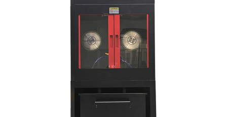
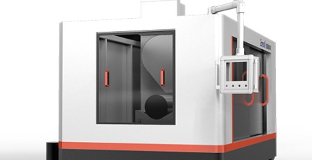
Тип станка: ESO-GM. The tube wall is brittle and hollow, and the requirement was high-precision
straight slicing, so Ensoll used the алмазную проволочную пилу ESO-GM, the model set aside for glass
tube work. The point of the choice is running stability and trajectory accuracy: it holds the cut path steady, reduces
what machine vibration and load fluctuation do to the kerf, and limits kerf offset and edge breakage on a thin wall,
which is what carries section dimensional accuracy and end-face integrity in practice.
- Тип охлаждающей жидкости: cutting oil. Cutting oil is the cooling and lubricating medium here. It improves
lubrication and heat transfer in the contact zone between wire and tube, lowers friction and heat build-up through the
cut, and reduces what thermal load does to the wall and the cut section. The practical effect is less risk of
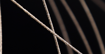
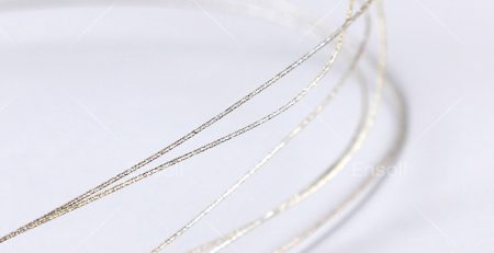
micro-cracks and chipping, plus better kerf dimensional stability and a cleaner end face. - Тип проволоки: полностью покрытая. A fully coated diamond wire raises the bond strength between grain and
core and limits grain pull-out and abnormal wire wear, so the grains keep cutting at a steady rate through the run.
Steady cutting means wire condition stops being a variable in kerf width, which is what keeps dimensional scatter and
end-face defects down on glass tube slices, and it also extends wire life.
3. Метод резки и преимущества машины
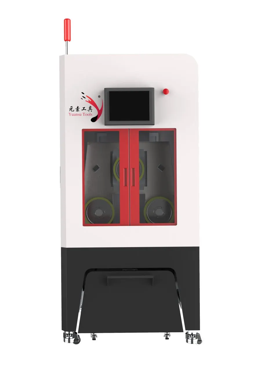
Gantry cutting method. The gantry structure gives the machine high overall rigidity and running
stability, and the top-down vertical feed helps hold the Петля из алмазной проволоки on a stable
path, so load variation has less effect on kerf position and dimensional accuracy in the tube slices. The machine also
carries a mist extraction system that clears the oil mist produced during cutting. On a small-diameter tube that
matters more than it sounds: keeping the work zone clear and clean is part of what makes the run repeatable.
Интеллектуальная система управления натяжением. The system adjusts wire tension in real time from the machining
state and supports both constant-tension and variable-tension modes, so the wire runs steadily through the cut. Steady
tension cuts trajectory drift, and it lowers the local load imbalance and wire breakage risk that tension variation
brings. On a tube, a wandering wire is not a cosmetic problem — it goes straight into kerf position and section
толщина.
Breakpoint memory. When the wire breaks or the machine stops abnormally, the system records the
current cutting position and the associated running state. After a wire change the cut resumes from that position,
which avoids the re-positioning error and repeat cutting that would otherwise cost both material and kerf quality, и
it keeps the slicing run continuous.
High-rigidity one-piece cast iron frame. The one-piece cast iron frame raises overall stiffness and
vibration resistance, and it lowers the effect of structural vibration and the small long-term deformation of a
running machine on the wire path. For a hard brittle part such as glass tube, high rigidity means less transient
vibration and less local load fluctuation during the cut, which is what keeps chipping and micro-cracking at the kerf
under control and gives dimensional accuracy and kerf quality a stable machine basis.
4. Parameter Settings and Cooling Method
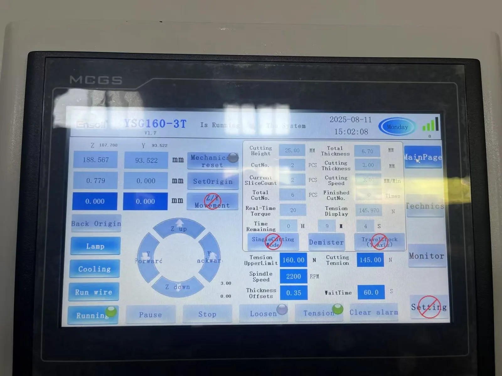
The table below is the parameter set used for the run, and the five sections reported in section 5 came off it. Проволока
speed and cutting load are the two readings that carry most of the wall-load control; wire travel speed at 3 mm/min is
low in absolute terms, which is normal for a small-diameter thin-wall part where the contact length between wire and
material is short and the load per unit length climbs quickly.
| Параметр | Значение |
|---|---|
| Диаметр проволоки (миллиметр) | 0.30 x 1880 |
| Скорость движения проволоки (мм/мин) | 3 |
| Ширина реза (миллиметр) | 12 |
| Cutting wire tension (N) | 145 |
| Скорость проволоки (М / сек) | 26 |
| Bow-forming time (s) | 60 |
| Нагрузка при резке (N·м) | 20 |
Cooling was cutting oil throughout, applied at the contact zone rather than flooded over the whole fixture. Oil was
chosen over water-based coolant for the same reason it wins on the other hard brittle materials Ensoll cuts: a
water-based fluid does not build a lubricating film strong enough at the grain-to-glass contact, so friction stays
high and the cut starts to depend on speed being kept low. Oil keeps the friction coefficient down, which lets the
wire hold a steady cutting state and keeps heat out of the wall.
5. Cutting Efficiency and Results
Five consecutive sections from the same tube were measured. TTV and thickness were taken on a vacuum-chuck
nine-point dual-head thickness gauge, roughness on a stylus profilometer to ISO 4287, and chipping by tool microscope.
All five sections came from the parameter set in section 4, so the scatter between them is process scatter, not a
comparison between different settings.
5.1 Данные теста TTV (единица измерения: миллиметр)
TTV (Изменение общей толщины) was measured with a nine-point grid on a vacuum chuck dual-head thickness gauge.
The gauge was warmed up to thermal equilibrium and calibrated against a standard thickness block before the run. Each
sample was cleaned and placed centred on the vacuum chuck, and negative-pressure clamping was used to hold the slice
flat so that warp and tilt did not enter the thickness reading. Thickness was then logged at the nine grid positions,
and TTV is the difference between the largest and smallest reading on that sample. Nominal section thickness was
3 mm from a tube of 12 mm outside diameter and 104 mm length. The method itself is described in more detail in our
nine-point TTV measurement note.
| Образец | Nine-point thickness readings (миллиметр) | Tmax | Tmin | TTV |
|---|---|---|---|---|
| S01 | 2.981, 2.971, 2.979 / 2.975, 2.976, 2.977 / 2.979, 2.974, 2.972 | 2.981 | 2.971 | 0.010 |
| S02 | 2.972, 2.970, 2.979 / 2.974, 2.973, 2.975 / 2.977, 2.972, 2.976 | 2.979 | 2.970 | 0.009 |
| S03 | 2.980, 2.977, 2.987 / 2.981, 2.983, 2.979 / 2.985, 2.980, 2.982 | 2.987 | 2.977 | 0.010 |
| S04 | 2.988, 2.988, 3.010 / 2.991, 2.996, 2.987 / 3.002, 2.982, 2.994 | 3.010 | 2.982 | 0.028 |
| S05 | 2.999, 3.003, 2.999 / 3.001, 3.000, 3.002 / 3.003, 2.999, 3.001 | 3.003 | 2.999 | 0.004 |
TTV across the five sections fell in the 0.004-0.028 mm range with a mean of 0.012 миллиметр, and apart from S04 every
section stayed at or below 0.010 миллиметр. For a 3 mm section that is a small thickness band, and it says the wire ran
steadily and the cut stayed on its trajectory. S04 is the outlier and it is also the only section whose readings run
to the plus side of nominal, which points at a local condition during that cut rather than at a limit of the process.
Whether that came from a tension excursion, a wire condition change or a piece of debris in the kerf cannot be settled
from the thickness data alone.
5.2 Допуск по толщине (единица измерения: миллиметр)
Thickness tolerance was calculated from the same nine-point data, using the 3.000 mm nominal section thickness as
reference and taking the signed deviation at each measured position.
| Образец | Средняя толщина (миллиметр) | Thickness deviation (миллиметр) |
|---|---|---|
| S01 | 2.976 | −0.024 |
| S02 | 2.974 | −0.026 |
| S03 | 2.982 | −0.018 |
| S04 | 2.993 | −0.007 |
| S05 | 3.001 | +0.001 |
| Максимальное положительное отклонение | +0.001 | |
| Максимальное отрицательное отклонение | −0.026 | |
| Допуск по толщине | ±0.026 |
Average thickness came out at 2.976, 2.974, 2.982, 2.993 и 3.001 миллиметр, so deviations against the 3.000 mm nominal
were −0.024, −0.026, −0.018, −0.007 и +0.001 миллиметр. Four of the five sit slightly under nominal
and only S05 comes in over it, which gives a maximum positive deviation of +0.001 mm against a maximum negative of
−0.026 mm and a total band of 0.026 миллиметр. The distribution is close to the nominal and biased on the minus side,
which is the direction you want if the section still has a finishing allowance to spend. As a thickness control result
it is consistent: the wire loop process held the 3 mm section within ±0.026 mm over the batch.
5.3 Surface Roughness Ra (единица измерения: μм)
Surface roughness was measured to ISO 4287 with a stylus profilometer. Three representative positions —
centre, mid-left and mid-right — were taken on the cut end face of each section.
| Образец | Ra-1 | Ra-2 | Ra-3 | Среднее значение Ra |
|---|---|---|---|---|
| S01 | 0.72 | 0.68 | 0.75 | 0.72 |
| S02 | 0.65 | 0.71 | 0.68 | 0.68 |
| S03 | 0.78 | 0.74 | 0.81 | 0.78 |
| S04 | 0.91 | 0.86 | 0.94 | 0.90 |
| S05 | 0.63 | 0.67 | 0.65 | 0.65 |
Average Ra across the five sections ran from 0.65 Кому 0.90 мкм. S05 was the best cut face at 0.65 мкм, с
S02 and S01 close behind at 0.68 и 0.72 мкм. S03 rose to 0.78 μm and S04 was the highest of the set at
0.90 мкм, and on S04 all three positions read high together rather than one position spiking. That pattern
matters: a single high position is usually a local defect, whereas all three rising points to a change in the cutting
state over that section. Even so, 0.90 μm is still a low roughness figure, so the honest reading is that the
process delivers a good end face most of the time and that S04 has room for parameter tuning rather than representing
a ceiling.
5.4 Откалывание кромок (единица измерения: μм)
Chipping was quantified by tool microscope imaging on the section edges. The four edges of each 104 миллиметр (L) x
12 миллиметр (φ) specimen were cleaned and the magnification and measuring scale were calibrated before observation, then
each edge was scanned and any identifiable chipping was located, measured and recorded.
| Образец | Положение 1 | Положение 2 | Положение 3 | Положение 4 | Maximum chipping |
|---|---|---|---|---|---|
| S01 | 4.2 | 5.6 | 4.8 | 6.1 | 6.1 |
| S02 | 3.8 | 5.1 | 4.5 | 5.7 | 5.7 |
| S03 | 4.5 | 5.9 | 5.2 | 6.4 | 6.4 |
| S04 | 5.6 | 7.2 | 6.3 | 8.1 | 8.1 |
| S05 | 3.6 | 4.8 | 4.2 | 5.3 | 5.3 |
Individual readings spanned 3.6-8.1 μm and the mean of the five maximum values works out at about 6.3 мкм.
Given how thin the wall is, that is a small edge defect band, and it says the cutting state stayed stable enough to
suppress brittle fracture and crack propagation at the kerf. The ordering of the samples is also worth noting: S04 is
worst again at 8.1 мкм, and its worst position is the same relative corner where thickness and roughness also ran
high. A single section carrying all three flags is a coherent signal, not noise.
6. Summary
The trial worked, and the reason is the usual one: dedicated machine, matched wire and suitable parameters treated as
one set. Glass tube is a hard brittle material with obvious brittleness and low fracture toughness, and in cutting it
is sensitive to local load and to heat build-up, which is exactly how chipping, micro-cracks, end-face unevenness and
section thickness deviation start. Against the material behaviour, the tube wall and the straight-slicing requirement,
the work was organised along three lines — machine selection, wire matching and process parameters — so
that the cut ran stably while section accuracy and end-face quality stayed under control.
On machine selection, the requirement was motion stability, cutting accuracy and rigidity, and the answer was a
diamond wire loop cutting machine built for glass-type hard brittle work. Structural rigidity and running stability
give the wire a reliable base for continuous running and the workpiece a stable cut, which reduces what machine
вибрация, motion error and wire path fluctuation do to the cutting trajectory. Steady feed and motion control also
damp load fluctuation, so the wire and tube keep a consistent relative motion and the probability of kerf deviation and
local chipping drops.
On wire selection, the deciding properties were hardness and brittleness of the glass and the brittle fracture it
tends to produce. A diamond wire matched to glass cutting removes material through continuous abrasion, and matching
grain characteristics, wire diameter and wire condition keeps the load on any single grain low while still removing
material at a usable rate. That is what reduces chipping and micro-cracking from local stress concentration and
improves end-face integrity and consistency.
On parameters, wire running speed and feed were matched to the material, the wall structure and the target section
длина. The setting principle was steady cutting and even material removal: feed too fast raises the cutting load, и
a poor parameter match brings local heating, brittle failure and edge breakage. Keeping the removal process even is
what buys thickness consistency, end-face quality and edge integrity at the same time as reasonable efficiency.
Taken together with the measured section accuracy, thickness tolerance, Ra and edge quality, the conclusion is that a
diamond wire loop process with a matched machine, a matched wire and suitable parameters meets the requirements of
high-precision straight slicing of glass tube. This is a single five-section batch from one tube, so the numbers should
be read as a process indication rather than as a guaranteed capability window — but they are consistent enough
to carry into production planning.
Часто задаваемые вопросы
Can a diamond wire loop slice glass tube without cracking it?
Да, provided the load per unit length stays low. In this test a 12 mm outside diameter glass tube was cut into 3 mm sections with maximum edge chipping of 3.6-8.1 μm and no section loss, с использованием а 0.30 мм полностью покрытой проволоки при 3 mm/min wire travel, 145 N tension and 26 m/s wire speed. A tube is more sensitive than a solid bar because the wall is thin and gives way locally before the whole section does, so clamping stiffness and feed stability matter as much as the wire itself.
What TTV can be expected when slicing thin-wall glass tube?
On this batch TTV measured by the nine-point vacuum chuck method ran 0.004-0.028 mm with a mean of 0.012 миллиметр, and four of the five sections stayed at or below 0.010 mm on a 3 mm nominal section. TTV on a tube is driven mainly by wire path stability and by how well the slice is held flat during measurement, so the vacuum chuck reference plane matters as much as the cut.
Why was cutting oil used instead of water-based coolant for the glass tube?
Oil builds a lubricating film at the grain-to-glass contact that water-based fluids do not, and that film is what keeps friction and friction heat out of a thin wall. In this run oil cooling combined with 145 N tension and a 3 mm/min wire travel gave a stable cut, with average Ra of 0.65-0.90 μm and chipping held to 3.6-8.1 мкм. The machine also carries mist extraction, which is a practical requirement once you commit to oil.
Is a fully coated wire better than a plain wire for glass tube slicing?
For this application it is the better default. A fully coated wire holds the grains more firmly, which limits grain pull-out and abnormal wear, so the wire keeps removing material at a steady rate instead of drifting as it wears. On a thin wall, a wire whose cutting behaviour changes mid-run turns directly into kerf width scatter and end-face variation, so wire consistency is worth paying for.
How much thickness tolerance is realistic on 3 mm glass tube sections?
This run held ±0.026 mm against a 3.000 mm nominal, with averages between 2.974 и 3.001 mm and four of five sections slightly under nominal. The bias toward the minus side is convenient because it leaves material for a finishing pass. If the section is a finished dimension, the cleaner route is a small dimensional compensation on the next run rather than chasing it with parameter changes.
Why did one section in the batch come out worse than the others?
S04 was the outlier on all three quality measures at once: highest TTV at 0.028 миллиметр, highest average Ra at 0.90 μm and highest chipping at 8.1 мкм, and its worst chipping position sits at the same relative corner where thickness and roughness also read high. A section that flags on three independent measures usually means something changed during that cut — a tension excursion, a wire condition change or debris in the kerf. The thickness data alone cannot separate those causes.
More general questions on wire choice, coolant and parameter matching are collected in our Часто задаваемые вопросы о технологии резки алмазной проволочной петлей.
Технический контент проверен инженерной командой Ensoll – производитель алмазной проволочной петли с 10+ years of
production experience.