Contour Cutting Borosilicate Glass with Diamond Wire Loop: 10 mm Circle Test Data
Sample testing for a European client (Company O) · Ring diamond wire contour cutting process
Overview
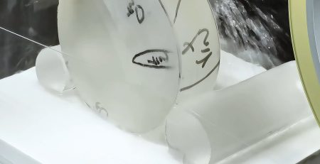
This report documents circular contour cutting of borosilicate glass using a ring diamond wire cutting system. The evaluation covers equipment and wire selection, cutting methodology, process parameters, and the resulting thickness uniformity, dimensional accuracy, surface quality, and edge integrity of the cut parts. Test results indicate that a vertical multi-axis ring diamond wire machine, oil-based cooling and lubrication, and appropriately matched process parameters deliver stable and accurate circular profile cutting of borosilicate glass with controlled edge chipping.
1. Test Specimen
| Parameter | Value |
|---|---|
| Material | Borosilicate glass |
| Hardness | approx. 6–7 Mohs |
| Workpiece dimensions | 80 mm × 80 mm × 10 mm |
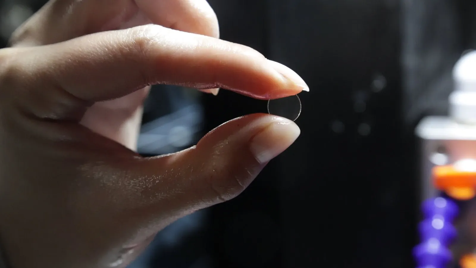
| Cut geometry | Circular contour, Ø10 mm |
Borosilicate glass is hard and brittle, with a strong tendency to chip at the cut edge and to develop localised micro-cracks during machining. A circular contour also places high demands on dimensional accuracy and trajectory stability, since any deviation shows up directly as an out-of-round profile.
2. Equipment and Wire Selection
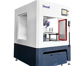
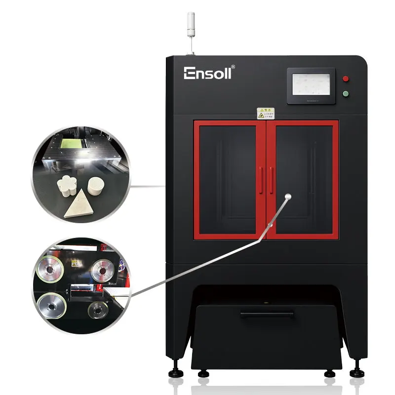
Equipment: ESS200-4T. Given the material characteristics of borosilicate glass and the requirement for contour cutting of a Ø10 mm circular profile, Ensoll selected the ESS200-4T vertical contour cutting system together with the ring diamond wire process. The vertical configuration maintains a stable circular cutting trajectory and reliable profile formation.
Coolant: oil-based cutting. Cutting oil is used as the cooling and lubricating medium. It improves lubrication and heat dissipation in the contact zone between the diamond wire and the borosilicate glass, reduces friction and localised heat accumulation during cutting, and limits fluctuation in cutting load and the effect of local temperature rise on the glass. This helps suppress chipping, micro-cracking and dimensional deviation in circular contour cutting.
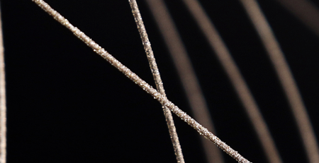
Wire: fully plated. A fully plated diamond wire was selected. The plated construction improves the bonding strength between the diamond abrasive grains and the wire core and provides a more uniform grain distribution. This sustains a continuous and stable material removal rate, reduces grain pull-out and wire wear, and contributes to lower chipping, micro-cracking and dimensional variation when cutting circular contours in borosilicate glass.
3. Cutting Method and Equipment Advantages
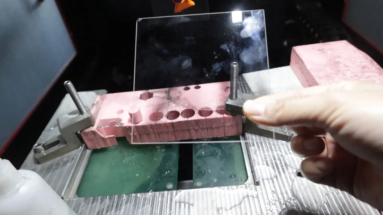
Vertical cutting configuration. The workpiece is clamped vertically and the ring diamond wire cuts vertically into the material, providing stable clamping and cutting conditions for a circular contour in borosilicate glass. Proper control of workpiece positioning and the entry sequence reduces fluctuation in cutting force, lowers the risk of edge break-out, and improves the accuracy of the circular profile.
Vertical wire cutting structure. The diamond wire traverses along the programmed cutting path while cutting oil lubricates and cools the contact zone, reducing friction and the effect of localised heat accumulation on the material. This structure helps maintain process stability and limits the influence of local thermal effects and fluctuation in cutting conditions on profile dimensions and edge quality.
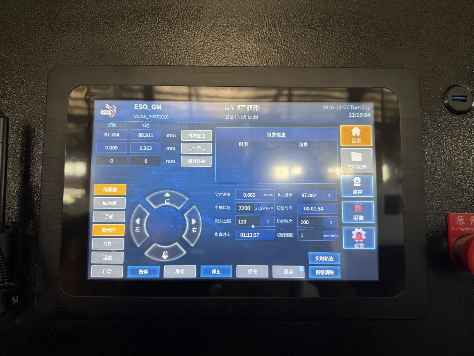
Real-time trajectory display. The cutting trajectory and machine status are displayed in real time during machining, allowing the operator to monitor execution of the circular contour, detect trajectory deviation or abnormal operation promptly, and adjust according to actual machining conditions. This improves control of the cutting path and the consistency of circular profile formation.
Multi-axis coordinated control. Coordinated multi-axis motion enables continuous cutting of the circular contour, keeping the machine trajectory aligned with the programmed path. Well-matched multi-axis control reduces trajectory deviation during contour transitions and motion, improving profile accuracy, dimensional consistency and process stability.
Independent wire-diameter compensation. Wire-diameter compensation is set independently according to the diameter of the diamond wire in use, correcting the influence of wire diameter on the actual cut profile and dimensions. When switching to a wire of a different diameter, the machining program does not need to be redrawn — only the compensation parameter is adjusted. This simplifies process changeover and improves the dimensional accuracy of borosilicate glass contour cutting.
Wire-break position memory. The system records and restores the wire-break position. If the diamond wire breaks, machining can resume from the position recorded by the system, reducing the effect of re-positioning and repeat cutting. This limits the impact of a wire break on the continuity of circular contour cutting, reduces unnecessary material loss, and improves yield.
4. Process Parameters and Cooling Method
| Parameter | Value |
|---|---|
| Wire diameter (mm) | 0.50 × 2305 |
| Wire traverse speed (mm/min) | 1 |
| Cutting width (mm) | 10 |
| Wire tension (N) | 100 |
| Wire speed (m/s) | 32 |
| Wire bow time (s) | 60 |
5. Cutting Performance and Results
5.1 TTV Test Data (Unit: mm)
Total Thickness Variation (TTV) was measured using a nine-point grid, dual-probe thickness gauging method on a vacuum-chuck stage. The measurement was applied to Ø10 mm circular contour parts produced by ring diamond wire cutting of borosilicate glass. The nominal specimen thickness was 10.000 mm.
| Sample | Nine-point thickness readings | Tmax | Tmin | TTV |
|---|---|---|---|---|
| S01 | 9.994, 9.996, 9.998 9.997, 10.000, 10.002 10.001, 10.004, 10.006 |
10.006 | 9.994 | 0.012 |
| S02 | 9.988, 9.991, 9.994 9.993, 9.997, 10.000 9.999, 10.003, 10.006 |
10.006 | 9.988 | 0.018 |
| S03 | 9.978, 9.982, 9.986 9.985, 9.990, 9.994 9.997, 10.000, 10.003 |
10.003 | 9.978 | 0.025 |
Assessment. Across the three borosilicate glass samples, measured thicknesses fell within 9.994–10.006 mm (S01), 9.988–10.006 mm (S02), and 9.978–10.003 mm (S03), with corresponding TTV values of 0.012, 0.018 and 0.025 mm. All three samples hold TTV within 0.025 mm on a 10 mm nominal thickness, confirming that the ring diamond wire process maintains good thickness uniformity in circular contour cutting of borosilicate glass.
5.2 Thickness Tolerance Data (Unit: mm)
Thickness tolerance was evaluated by multi-point grid measurement on the circular borosilicate glass parts produced by ring diamond wire cutting. Several measurement points were taken within the effective measurement area of each specimen, the measured thickness was recorded at each point, and the deviation from the nominal thickness was calculated so that the overall thickness deviation range could be determined.
| Sample | Mean thickness | Thickness deviation |
|---|---|---|
| S01 | 10.000 | 0.000 |
| S02 | 9.997 | −0.003 |
| S03 | 9.991 | −0.009 |
| Maximum positive deviation | — | +0.006 mm |
| Maximum negative deviation | — | −0.022 mm |
| Thickness tolerance band | — | ±0.014 mm |
Assessment. Against a nominal thickness of 10.000 mm, mean thicknesses of the three samples were 10.000 mm, 9.997 mm and 9.991 mm, with deviations of 0.000 mm, −0.003 mm and −0.009 mm respectively. The overall thickness tolerance band was ±0.014 mm, indicating good thickness consistency in circular contour cutting of borosilicate glass.
5.3 Surface Roughness Ra Data (Unit: μm)
Surface roughness (Ra) was measured by stylus profilometry on the circular borosilicate glass parts after ring diamond wire cutting. Representative measurement positions were taken at the centre and on both sides along the cut end face, surface profile data was acquired with a stylus profilometer, and the roughness parameter Ra was recorded at each position.
| Sample | Ra-1 | Ra-2 | Ra-3 | Mean Ra |
|---|---|---|---|---|
| S01 | 0.48 | 0.55 | 0.51 | 0.51 |
| S02 | 0.43 | 0.49 | 0.46 | 0.46 |
| S03 | 0.61 | 0.72 | 0.66 | 0.66 |
Assessment. Mean Ra across the three samples was 0.51, 0.46 and 0.66 μm, with individual readings between 0.43 and 0.72 μm. The narrow spread across measurement positions on each part indicates a uniform surface finish along the cut face, consistent with stable single-direction ring wire cutting.
5.4 Edge Chipping Data (Unit: μm)
Edge chipping was quantified by optical imaging on a toolmaker’s microscope. Specimen edges were cleaned before measurement, and the magnification and measurement scale of the instrument were calibrated. The circumference of each specimen was then inspected under the microscope, and measurable chipping at the cut edge was recorded at four positions per sample, with the maximum value retained.
| Sample | Position 1 | Position 2 | Position 3 | Position 4 | Max. chipping |
|---|---|---|---|---|---|
| S01 | 4.5 | 5.2 | 6.1 | 5.7 | 6.1 |
| S02 | 3.8 | 4.6 | 5.4 | 4.9 | 5.4 |
| S03 | 6.5 | 8.2 | 9.4 | 7.6 | 9.4 |
Assessment. Four-point edge inspection of the three borosilicate glass parts gave maximum chipping values of 6.1, 5.4 and 9.4 μm respectively, with all measurement points falling within 5.4–9.4 μm. Chipping was small overall; S01 and S02 showed the least edge damage, while S03 showed the largest maximum chipping at 9.4 μm.
6. Conclusion
The machining quality of the circular contour cut in this borosilicate glass trial depended mainly on three factors working together: a purpose-built cutting machine, the cooling and lubrication method, and correctly matched process parameters. Borosilicate glass is markedly hard and brittle, tends to chip and develop localised micro-cracks during cutting, and the circular contour places high demands on dimensional accuracy and trajectory stability.
Equipment. For the trajectory control and machining accuracy required by circular contour cutting of borosilicate glass, Ensoll selected the ESS200-4T vertical contour cutting system. The machine is suited to complex contour work, follows the programmed path to execute circular cuts, and provides the mechanical basis for profile formation and dimensional control.
Cooling and lubrication. Cutting oil was used as the cooling and lubricating medium. During cutting the diamond wire remains in continuous contact with the borosilicate glass and the abrasive grains grind the material continuously, generating friction heat in the contact zone. Cutting oil improves lubrication and heat dissipation at the wire–glass interface, reduces friction and localised temperature rise, and helps suppress thermal effects and edge chipping.
Process parameters. Wire speed, feed rate and other key parameters were matched to the hard-brittle characteristics of borosilicate glass and to the requirements of a Ø10 mm circular contour. Parameters were set to maintain stable wire travel and continuous material removal, avoiding feed rates high enough to raise cutting load or degrade edge quality.
Overall. Taken together with the dimensional measurements and machining quality evaluation of the circular contour, the combined use of a purpose-built vertical contour cutting machine, oil-based cutting, and appropriately matched process parameters provides a reliable process basis for accurate profile formation and edge quality control in borosilicate glass. The results demonstrate that ring diamond wire contour cutting is a viable route for precision circular profiles in hard-brittle glass.