다이아몬드 와이어 루프로 실리콘 봉 정밀 절단
추상적인: This article presents a comprehensive study on the precision slicing of silicon rods using a 다이아몬드 와이어 루프. The test workpiece was a φ330 mm × 500 mm silicon rod sourced from a European customer, sliced into 10 mm-thick wafers on an Ensoll ESC600-4T single-cantilever machine. We report the cutting parameters, cooling strategy, and quantitative quality metrics including Total Thickness Variation (TTV), dimensional tolerance, 표면 거칠기 (Ra), and edge chipping. The results demonstrate that an optimized diamond wire loop process can achieve stable, high-precision silicon slicing suitable for downstream semiconductor and photovoltaic applications.
- A φ330 mm × 500 mm silicon rod was sliced into 10 mm wafers on the Ensoll ESC600-4T diamond wire loop machine (0.50 mm wire, 38 엠/초, 210 N tension).
- Optimizing feed parameters cut TTV from 0.170 mm to 0.070 mm across three test runs.
- Average surface roughness stayed below 1 최소한의 가장자리 칩을 가진 μm Ra.
1. 소개
실리콘은 현대 반도체 및 태양광 산업의 중추. 단결정 실리콘 웨이퍼 매우 엄격한 공차를 요구: 최소한의 두께 변화, 낮은 표면 거칠기, 거의 제로의 가장자리 칩. 대구경 실리콘 막대에서 이러한 규격을 달성하는 것은 실리콘이 경단하고 취성하기 때문에 어렵다, 상대적으로 낮은 파단 인성을 가짐. 연마 절단 중, 집중된 열 및 기계적 하중이 취성 균열을 유발할 수 있다, 지하 미세 균열을 전파시키고, 가장자리 칩과 두께 불일치를 유발한다.
이러한 문제를 해결하기 위해, Ensoll Tools는 실리콘 막대의 고정밀 선형 절단을 위한 전용 공정을 설계했으며. 이 접근법은 연속 수냉을 결합해 절단 구역 온도 상승을 억제한다, optimized feed parameters matched to the material, and a custom single-cantilever diamond wire loop cutting machine (ESC600-4T). By aligning machine structure, cooling conditions, and cutting parameters, the process minimizes thermal and mechanical damage to both the wafer surface and edges, delivering the dimensional accuracy, thickness uniformity, and surface quality required for advanced silicon applications.
2. Test Object and Material Properties
The workpiece for this study was supplied by a European customer (referred to as Customer F). The key material and geometry data are summarized below:
- 재료: Silicon rod
- 경도: Mohs ~6.0–6.5
- Workpiece dimensions: φ330 mm × 500 밀리미터 (L)
- Target slice thickness: 10 밀리미터
Silicon’s combination of high hardness and brittleness makes it a classic representative of hard-and-brittle materials. Any cutting technology applied to silicon must simultaneously control abrasive wear, heat accumulation, and brittle-mode material removal.
The same hard-and-brittle behaviour sets the practical feed limit when cutting alumina ceramics, where chipping rather than tool wear is the binding constraint.
3. Machine and Wire Selection
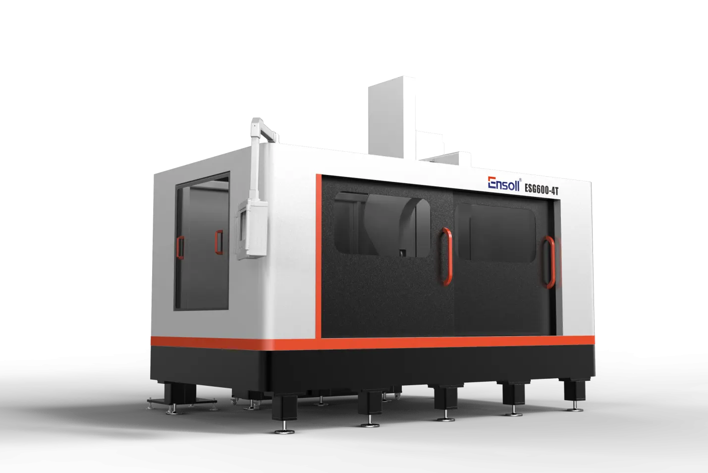
The cutting trials were performed on an Ensoll ESC600-4T single-cantilever diamond wire loop cutting machine. This model was developed specifically for large-diameter silicon-rod slicing, taking into account the material’s hardness, 취 성, and the geometric tolerances demanded by semiconductor-grade processing.
- 냉각수: Water. Water offers high specific heat capacity and excellent convective heat transfer, making it ideal for reducing cutting-zone temperature and flushing away silicon debris. Continuous water supply improves interface cleanliness, cutting stability, and final surface quality.
- Wire type: Fully electroplated diamond wire loop. The electroplated bond ensures high-density, uniform diamond-grain distribution and strong grain retention. This configuration maximizes effective cutting edges, improves wire durability, and reduces surface damage and edge chipping.
4. 절단 방법 및 기계 장점
The ESC600-4T integrates several structural and control features that directly benefit silicon-rod slicing:
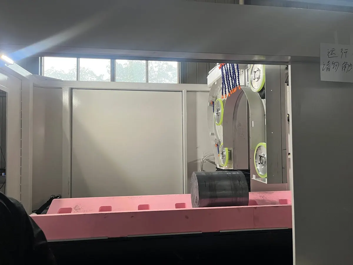
- Gantry cutting architecture: A high-rigidity gantry frame drives the cutting assembly vertically. This layout maintains structural stability and motion accuracy throughout the cut, suppressing vibration and trajectory deviation. The result is improved perpendicularity and dimensional consistency across each slice.
- Moving-head, fixed-workpiece design: The cutting assembly moves while the silicon rod remains stationary. Eliminating workpiece motion preserves the machining reference and allows a more compact machine footprint for the same billet size.
- Adjustable V-support platform: An adaptable V-type support structure can be repositioned to match the rod diameter, ensuring stable clamping and accommodating a range of silicon-rod specifications.
- Hydraulic loading table: A hydraulic lift handles rod loading and positioning, reducing impact and positional drift during manual handling. The lift also retracts clear of the support structure during cutting, preventing interference.
- 지능형 장력 제어: The tension system continuously adjusts wire tension in response to run-time state and wire-diameter wear, keeping the diamond wire loop in a stable tension window. When idle, the system relaxes tension to minimize long-term load on both the wire and guide-wheel grooves; upon restart, working tension is restored rapidly.
5. 절단 매개변수 및 냉각
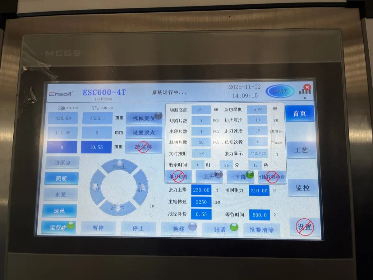
The principal cutting parameters were selected based on the silicon material properties, 이 10 mm target slice thickness, and preliminary process verification. The parameter set is summarized in Table 1.
| 매개변수 | 값 |
|---|---|
| 와이어 직경 (밀리미터) | 0.50 × 3,570 |
| 피드 속도 (mm / 분) | 15 / 18 / 25 |
| 절단 폭 (밀리미터) | 330 |
| 와이어 장력 (N) | 210 |
| 와이어 속도 (엠/초) | 38 |
| Wire bow time (초) | 200 |
Water was supplied continuously as the coolant throughout all cuts. Three feed speeds were evaluated—15, 18, 그리고 25 mm/min—to investigate the influence of removal rate on slice quality.
6. 절단 결과
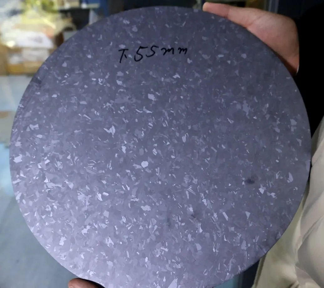
Three slices (labeled S01, S02, and S03) were produced and subjected to metrological inspection. Each sample was measured for Total Thickness Variation (TTV), dimensional tolerance, 표면 거칠기 (Ra), and edge chipping.
6.1 총 두께 변동 (TTV)
TTV was measured using a vacuum-chuck nine-point grid dual-probe thickness gauge. The equipment was thermally equilibrated and calibrated with certified thickness blocks before testing. Samples were cleaned in a dust-free environment, centered on the vacuum chuck, and held flat by negative pressure to minimize warpage-induced error.
| 시료 | Nine-point thickness (밀리미터) | Tmax (밀리미터) | Tmin (밀리미터) | TTV (밀리미터) |
|---|---|---|---|---|
| S01 | 9.780, 9.750, 9.760, 9.820, 9.650, 9.720, 9.790, 9.730, 9.770 | 9.820 | 9.650 | 0.170 |
| S02 | 9.926, 9.977, 9.952, 9.961, 9.936, 9.885, 9.948, 9.920, 9.950 | 9.977 | 9.885 | 0.092 |
| S03 | 10.006, 10.071, 10.075, 10.073, 10.005, 10.066, 10.032, 10.048, 10.058 | 10.075 | 10.005 | 0.070 |
평가: 9점 TTV 데이터는 S03이 가장 우수한 두께 균일성을 제공했음을 보여주며 (0.070 밀리미터), S01은 가장 큰 변동을 나타냈습니다 (0.170 밀리미터). 급송 속도가 15 mm/분에서 25 mm / 분, TTV가 단조롭게 개선되었으며, 이는 적절한 냉각 및 장력 제어와 결합할 때, 다소 높은 급송 속도가 절삭 공정을 안정화하고 두께 변동을 줄일 수 있음을 시사합니다.
6.2 두께 치수 허용차
두께 허용차는 명목 두께 10.000 mm에 대해 동일한 9점 그리드 데이터를 사용하여 평가되었습니다. 각 측정 지점에 대해 양수 및 음수 편차가 계산되었으며, 세 개의 슬라이스 전체에서 요약되었습니다.
| 시료 | 평균 두께 (밀리미터) | 두께 편차 (밀리미터) |
|---|---|---|
| S01 | 9.641 | −0.359 |
| S02 | 9.939 | −0.061 |
| S03 | 10.048 | +0.048 |
| 최대 양수 편차 | +0.048 | — |
| 최대 음수 편차 | −0.359 | — |
| 전체 두께 허용차 | ±0.359 | — |
평가: 두께 편차는 주로 음수였다. S01은 뚜렷한 얇음 편향을 보였다 (−0.359 mm), 이는 전체 허용 오차 범위를 넓혔다. S02와 S03은 점차 명목 치수에 접근하였다, 이는 더 높은 이송 속도에서 치수 제어 안정성이 향상되었음을 나타낸다. 이 추세는 이송 속도 최적화가 두께 정확성을 위한 중요한 수단임을 확인시킨다 실리콘 웨이퍼 절단.
6.3 표면 거칠기 (Ra)
표면 거칠기는 ISO에 따라 스타일러스 프로파일로미터로 측정되었다 4287. 측정 방향은 지배적인 표면 질감 방향과 일치시켰다. 각 슬라이스에서 세 위치를 검사하였다: 중앙, 왼쪽 중간, 오른쪽 중간.
| 시료 | Ra-1 (μm의) | Ra-2 (μm의) | Ra-3 (μm의) | 평균 Ra (μm의) |
|---|---|---|---|---|
| S01 | 0.860 | 0.640 | 0.690 | 0.730 |
| S02 | 0.910 | 0.960 | 0.680 | 0.850 |
| S03 | 0.760 | 0.670 | 0.800 | 0.743 |
평가: 평균 Ra 값 범위는 0.730 μm에서 0.850 μm의, 전체 분포는 0.640–0.960 μm였다. 각 슬라이스의 측정 위치 간 작은 변동은 균일한 표면 질감을 나타낸다, confirming that the diamond wire loop run and material removal remained stable throughout the cut. These Ra levels are consistent with high-quality abrasive slicing of silicon and compare favorably with results reported in our precision slicing of metal tubes case study.
6.4 엣지 치핑
Edge chipping was quantified by optical microscopy on all four edges of each slice. Samples were cleaned, the microscope scale was calibrated, and all four sides were scanned sequentially.
| 시료 | 위치 1 (μm의) | 위치 2 (μm의) | 위치 3 (μm의) | 위치 4 (μm의) | Max chipping (μm의) |
|---|---|---|---|---|---|
| S01 | 5.6 | 7.2 | 6.4 | 8.1 | 8.1 |
| S02 | 6.3 | 8.5 | 7.1 | 9.2 | 9.2 |
| S03 | 5.1 | 6.8 | 7.4 | 8.6 | 8.6 |
평가: Chipping sizes ranged from 5.1 μm에서 9.2 μm의, with mean maximum chipping of 8.6 μm의. The relatively narrow distribution across all samples indicates stable material removal at the kerf boundary. Edge integrity at this level is acceptable for many semiconductor preprocessing steps and can be further improved with parameter refinement.
7. 결론
The silicon-rod slicing trials demonstrate that a well-matched combination of machine architecture, 냉각 시스템, and cutting parameters can deliver high-precision results on large-diameter silicon billets. The key findings are:
Shops specifying equipment for large-diameter work can compare gantry and cantilever architectures in our overview of the 다이아몬드 와이어 톱 절단기.
- Machine structure matters. The single-cantilever ESC600-4T gantry design provides the motion stability and clamping adaptability needed for φ330 mm silicon rods. By isolating machine vibration from the wire trajectory, the cantilever layout establishes a solid foundation for thickness control and cutting consistency.
- Cooling is non-negotiable. Continuous water cooling effectively suppresses cutting-zone temperature rise, flushes abrasive debris, and maintains a clean wire–workpiece interface. The reduction in thermal load and particulate contamination directly translates to more stable cutting and better surface integrity.
- Feed-rate optimization pays off. Raising the feed speed from 15 mm/분에서 25 mm/min progressively reduced TTV from 0.170 mm to 0.070 밀리미터. This confirms that, within the tested window, a faster feed can stabilize the material-removal process and improve thickness uniformity when paired with adequate cooling and tension control.
Collectively, the TTV, thickness tolerance, 표면 거칠기 (Ra), and chipping data validate that the optimized 다이아몬드 와이어 루프 process on the ESC600-4T is capable of producing silicon slices that meet the stringent requirements of photovoltaic and semiconductor downstream processing. The results provide a practical process baseline for engineering-scale silicon-rod slicing and can be adapted to other hard-and-brittle materials of comparable hardness and geometry.
For more information on Ensoll’s diamond wire loop solutions for silicon, 자성 재료, 도예, 및 금속, explore our precision slicing guides or contact our engineering team.
These results sit alongside our wider work on silicon wafer slicing, where the same parameters are tuned for thinner wafers.자주 묻는 질문
What TTV can a diamond wire loop achieve when slicing silicon rods?
In this ESC600-4T test on a φ330 mm silicon rod, total thickness variation (TTV) improved from 0.170 mm to 0.070 mm as feed parameters were optimized across three runs.
What surface roughness does diamond wire loop slicing produce on silicon?
Average Ra stayed below 1 μm across samples in this study — smooth enough to reduce or eliminate downstream lapping for many applications.
Which machine was used for this silicon rod slicing study?
The Ensoll ESC600-4T single-cantilever diamond wire loop cutting machine, running a 0.50 mm diamond wire loop at 38 m/s wire speed and 210 N tension.
Why use a diamond wire loop instead of a slurry saw for silicon rods?
The loop cuts with fixed diamond abrasive in a water-cooled, single-direction pass, giving a narrower kerf, less sub-surface damage, and shorter cycle times than loose-abrasive slurry sawing.
엔솔 엔지니어링 팀이 검토한 기술 내용 — 다이아몬드 와이어 루프 제조업체 10+ 다년간의 생산 경험을 가진 회사.